Document Actions
Optical tweezers explained
Light possesses both energy and momentum. An interaction between radiation and matter can result in an exchange of momentum. Consider a dielectric sphere placed in a laser beam (figure 1a). The sphere acts like a miniature lens; the refraction or reflection of light at a dielectric interface alters the direction, and hence the momentum of the light. Due to the spatial intensity profile of the laser beam more light is refracted towards left than the right. The light therefore gains overall momentum towards the left which, by Newton's third law, means that the sphere gains momentum in the opposite direction (towards the right, or more precisely, towards the highest laser intensity). Closer examination reveals that the force is related to the gradient of laser intensity, and it is therefore often referred to as gradient force. As a consequence, the sphere is drawn into the region of highest light intensity.
While this mechanism confines the sphere in the directions perpendicular to the beam propagation, another process is used to trap in the direction parallel to the beam. When placed in the path of a laser beam, the sphere will feel 'radiation pressure' caused by the stream of photons scattering off its surface, giving the sphere momentum in the direction of the beam (this effect can be seen on a much larger scale in the field of astronomy—a comet's tail as seen from earth is caused by radiation pressure from the sun). If the laser beam is focused very tightly (figure 1b) there is also a gradient force against the propagation direction of the beam which can balance the radiation pressure from the beam. In this manner, a three-dimensional single beam trap can be created to trap microscopic particles.
 |
 |
| Figure 1a) Lateral Trapping | Figure 1b) Axial Trapping |
Gradient force pulls particles towards the highest laser intensity in transverse direction (a) and for a strongly focussed beam also in longitudinal direction (b). Click on figures (1a) and (1b) for larger versions.
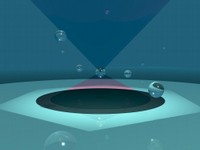
Fly-by Animation of a Trapped Bead
An important quantity in trapping experiments is the refractive index difference between the beads and the solution in which they are suspended—a typical situation would be to have the beads with refractive index around 10% greater than the surrounding solution. The images here are simulations using a larger refractive index difference (around 20%) between particle and medium, to allow the beads to be seen more clearly. This difference is the reason why the cone angle of the beam leaving the bead (the bead is placed slightly below focal point) is noticeably smaller than the incident cone angle.
 |
c_flyby.avi |
|
Click to enlarge—37 kB
(Full Size 1024x768)
|
click to play movie
(400x400x14s —5.32MB)
|